

If you’re working with Cisco routers and need to set up Integrated Routing and Bridging (IRB) using VLANs, this guide is for you. We’ll walk through a sample configuration that enables routing between VLANs while maintaining Layer 2 bridging within each VLAN.
What Is IRB in Cisco?
IRB (Integrated Routing and Bridging) allows a Cisco device to perform both Layer 2 bridging and Layer 3 routing on the same interface. This is useful when you want to route between VLANs but still support legacy bridging protocols.
Example Topology:
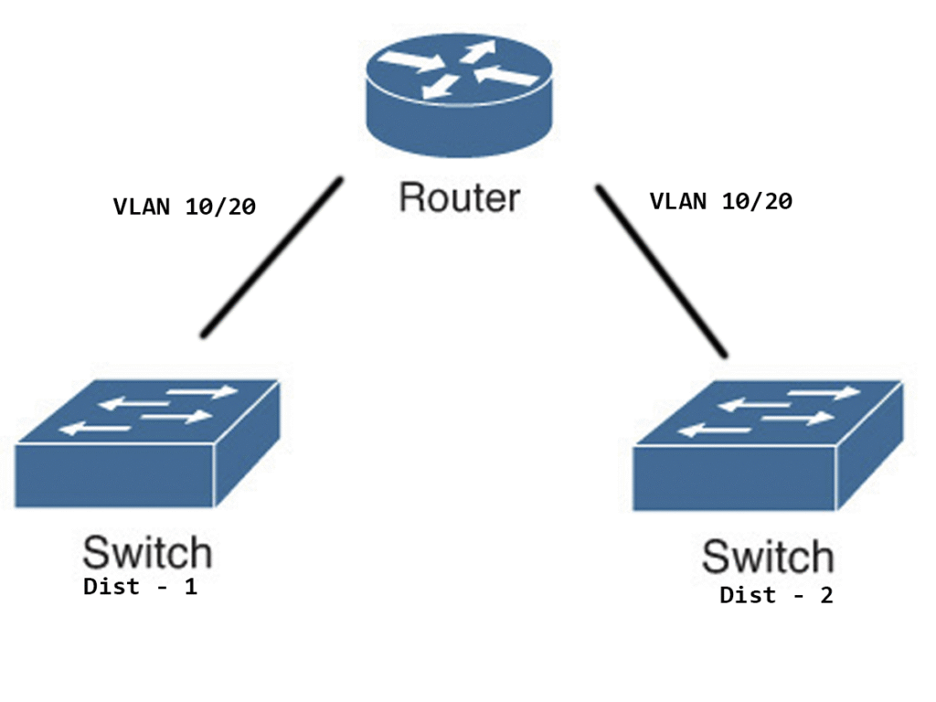
Step 1: Enable IRB and Define Bridge Groups
Start by enabling IRB globally and defining your bridge groups:
bridge irb
bridge 10 protocol ieee
bridge 10 route ip
bridge 20 protocol ieee
bridge 20 route ip
bridge irb: Activates IRB functionality.bridge <ID> protocol ieee: Enables IEEE 802.1D bridging.bridge <ID> route ip: Allows IP routing within the bridge group.
Step 2: Configure VLAN Subinterfaces
Assign VLANs to subinterfaces and bind them to bridge groups:
interface FastEthernet0/2.10
 encapsulation dot1Q 10
 bridge-group 10
 no shutdown

interface FastEthernet0/2.20
 encapsulation dot1Q 20
 bridge-group 20
 no shutdown

interface FastEthernet0/1.10
 encapsulation dot1Q 10
 bridge-group 10
 no shutdown

interface FastEthernet0/1.20
 encapsulation dot1Q 20
 bridge-group 20
 no shutdown
Each subinterface is tagged with a VLAN ID and assigned to a bridge group. The no shutdown command ensures the interface is active.
Step 3: Create Bridge Virtual Interfaces (BVIs)
BVIs act as the routed interface for each bridge group:
interface BVI10
 ip address 172.20.1.1 255.255.255.252
 no shutdown

interface BVI20
 ip address 172.20.2.1 255.255.255.252
 no shutdown
These interfaces allow Layer 3 routing between VLANs while maintaining Layer 2 bridging within each VLAN.
Step 4: Save Your Configuration
Once everything is set up, save your configuration:
end
write memory
This ensures your settings persist after a reboot.
Final Overview
| VLAN | Bridge Group | Interfaces | BVI IP Address |
|---|---|---|---|
| 10 | 10 | Fa0/1.10, Fa0/2.10 | 172.20.1.1/30 |
| 20 | 20 | Fa0/1.20, Fa0/2.20 | 172.20.2.1/30 |
Conclusion
Now your Cisco router is now set up to route between VLANs while bridging within each VLAN. This hybrid approach is ideal for networks that need both legacy support and modern routing capabilities.